Friday, December 12, 2014

The final blog post

We have come along way and we hope that everyone enjoys our project.


These pictures were just us on the expo early. We wanted to get a good spot and assemble our project in time for the expo.

Here is a video! We managed to get it to move straight, but we still have to give it a little push. If we tried to increase the duty cycle to high we end up blowing a fuse. We are still pretty proud of it.


Here is a picture of the entire project finished. 

That's us! Sadly one of our group member could not make it to the meeting.

Regarding the end of the project, we believe we did fairly well. We took a lot of the concepts we learned in the class and tried to integrate them in the project. If we had managed our time a little more we might have been able to integrate the joystick and maybe some steering mechanism. We were also looking at changing out the gears. I think the main reason we can't get the chair to move with someone heavy on it is because our gear ratio's could have been better. However, what we found at the hardware store was the best combination we could find. Other than that, we also wished we had a made better decision about what to do for a laser cutting and 3d printing. We really wanted to incorporated something that could hold the joystick in place and protect it. Now looking back, I think we would of also incorporated the UML logo. We ended up just using a laser cut cardboard box, but it was way to big. Regardless if what we didn't do, we will learn from those mistakes and incorporate the process in future classes. 

Thursday, December 11, 2014

A slight problem, but also a bright side (Well, technically a dark side)


This is the set up we have. Starting from the top of picture we have the motor control module that came from the treadmill. Right below the bread board, is the power supply that we also took from the treadmill. As of right now, we are having difficulties integrating the joystick with the control module. Also, notice that we are using the older control module. The one that the group purchased could only take about 12 volts and it might have just been poor judgement on our part, but the new control module is no longer with us. However, the old one seems to work fine so we are OK with that. We will try our best to get it working.


But on the bright (dark) side, we painted the wooden frame and the chair. It looks a lot neater then it did before. Now we just have to do some testing tonight and hopefully have something for tomorrows expo. 

Set lasers to cut...a box


About a week ago, we posted some pictures of possible Solidworks designs for a box that could hold an Arduino and a joystick. Well, I had completely forgotten about those parts that I made and never uploaded them to Google Drive. I did attempt to go a computer lab and tried to make new ones, but due to time constraints I had make solid models and hope that we could just glue them together. However, Professor Sullivan was gracious enough to allow us to use a box that he already had spec'ed out. Without losing time he helped us cut out what we needed. The box was a little too tall to allow the joystick to stick out and have some movement, but we should be able to figure something out to adjust height. 

Monday, December 8, 2014

Coding is good for you

int PWM_OUT = 9;
float duty = 0.0;
int onTime;
void setup()
{
  pinMode(PWM_OUT, OUTPUT);
  pinMode(13, OUTPUT);
}
 
void loop()
{
  onTime = floor(duty*50);
  digitalWrite(PWM_OUT, HIGH);
  digitalWrite(13, HIGH);
  delay(onTime);
  digitalWrite(PWM_OUT,LOW);
  digitalWrite(13, LOW);
  delay(50-onTime);


}​

*********************************************************************************
This code was written so that we could control the speed of the motor instead only disconnecting it and reconnecting it. I would also like to point out in the code is that a PWM had to be used in order for it to work properly. PWM stands for Pulse Width Modulation. This is how we control the motor itself. By varying the proportion of the duty cycle, it tells the motor how fast to spin and when to spin that fast. We are hoping that this could will help us when we trying to integrate the joystick into the project. 

Monday, December 1, 2014

Solidworks for days


Bottom Section


Side Section


Top section with a circle cut out for the joystick

So these Solidworks files were originally going to be for the box that would hold the Arduino and the joystick. Obviously this setup would just be a temporary part, but this allows the person to get an idea of what a finished product could look like if someone were to bring this project from start to finish.  These Solidworks files were never truly finished. They don't have the proper mates and the puzzle pattern on the outside to fully mesh a rectangular box together. We will continue to work on them until we have something.


Monday, November 24, 2014

This might just save us


What we have here is a DROK L298N Dual H-Bridge Robot Stepper Motor Control & Drives Module. In any type of moving “object, you want to be able to give it power when you want. What you don’t want is only two settings: full power or no power. What this device allows us to do is alternate between those two options without interruption. This the case with our project once the circuit is close, power is constantly being given unless we sever the connection. We mentioned in older posts that we attempted to use the older control module, but since it was so old we couldn’t see to get it to work. We went ahead and purchased this and surprisingly it was fairly cheap. This will benefit us when we integrate it with our Arduino board and joystick allowing us to stay connected and (hopefully) move the wheel chair on command. 

Monday, November 17, 2014

It's...ALIVE!


So we finally made some real progress! As you can see in this video posted below, we managed to give the motor power and at least move the wheels. Judging from how slow it turns though, we will need more power in order for it to move a person, let alone itself.


Thursday, November 13, 2014

Forward and Back


 We found this joystick online and it seems to be easily integrated into our system. As of right now, we would just like the wheel chair to be able to at least move forward and backwards. Turning side to side will be a much more challenging task. Also, we would like to be able to 3-D print a part to allow the joystick to stay stationary and to protect it a way. We will design a box that can hold it in place that is safe and easily accessible.

Tuesday, November 11, 2014

Almost there


This is a back view of the wheel chair and more or less the entire project. The only thing that is missing is the chair itself (which is somewhere in the background) and the joystick that should be implemented soon.

Sunday, November 9, 2014

An idea set in stone

So we have been busy at work on this project. We have managed to get together a couple times and boil everything done to what we are using for parts. We also have plenty of pictures.


This is a power source we hope to use. It came out of an old car that was not in use anymore. We hope that it can still hold somewhat of a charge.


We found 2 tires that came off an old bicycle. 


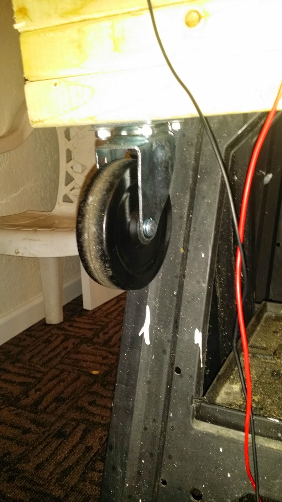
Caster wheels for the front of wheel chair


These movable bearings were purchased from a hardware store.


The motor that we ripped out of the poor treadmill. The pulleys you see on the left were also bought from a store. It took a long time to find a small pulley that would give us decent torque. That was the smallest we could find without spending too much money


This is just an overview of the gutted treadmill. We took a lot out of it


The top picture is the internal power supply that came with the tread mill. The picture right below it was the motor control unit. Because this treadmill is so old, we don't know if we can use this at all, but we can try.


Here is just a mess of everything else that we have been working on. All of the wires and soldering that have been going behind the scenes of the project. 

So here is what we have so far. As you can see in some of the pictures, the frame itself has already been built. Regarding the axle in some of the pictures, one of our group member's, Dean, machined the axle himself and had it threaded. This allowed us to lock the tires in and help give it a stable ride when we do some actual testing.


Monday, November 3, 2014

Some parts...

So after looking at what we really wanted to do, we went ahead and are going to attempt to make a electric wheel chair. This project will of course incorporate the skills we have learned in lab like Solidworks and Arduino. So far for the project, we somewhat have a list of what we want to be apart of the project.

The unfinished list includes:

  • We would like tires or wheels of some sort. So far we might be going with bicycle tires and regular caster wheels. As of right now, we are not too sure about where to position them. 
  • A base or frame. Probably going to be using plywood in this case because it's cheap and strong enough to hold a good amount of weight.
  • An axle
  • To drive the wheels, we looked at different types of motors. We thought about using a gasoline motor at first, but then found out it would be rather difficult to wire it in with an Arduino. We ended up just going with a motor taken out from an old treadmill.
  • A Power supply. Possibly using a car battery or some other source of power
  • A lot of wiring
  • Some type of control module
  • A device that can control the movement of the wheel chair (Joystick or steering wheel of some sort) 
This is a very rough list of what we want to do, but hopefully we should have a much better list and some pictures to show for progress in the coming blog posts. 

Monday, October 27, 2014

First group meeting!!

First group meeting today.  Excited to begin this project and see what we can create together! We have a couple of ideas, but we are leaning towards an electric wheel chair.


Something like this would be cool to do, but it is a little complex

Another cool and similar idea.